Enjoy. Tips, criticism, recommendations are gratefully accepted. Special thanks to Birdman for trusting me with his M4 for install & example pictures.I. Making basic MOSFET
II. Installing to v2 M4 gearbox
III. Installing to micro switch
IV. Installing to v3 AK gearbox
V. Installing to v6 Thompson gearbox
VI. Correcting AoE
VII. Radiusing shell window
VIII. Shimming
IX. Airseal mods
In progress 1. Cylinder head
2. Piston head
3. Air nozzle
X. Tappet trimming
XI. Barrel stabalization
Coming soonXII. Soldering deans
XIII. Preventing Premature Engagement
In progress 1. Short stroking
2. Heavier spring
3. Piston lightening & swiss cheesing
Part l. Making basic MOSFETHere is a guide on how to build and install a basic MOSFET. There are a handful of other ways to make MOSFET's; however, this is perhaps the easiest way I've found.
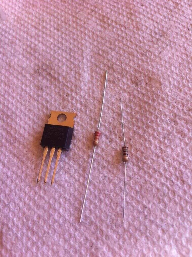
To start you will need:
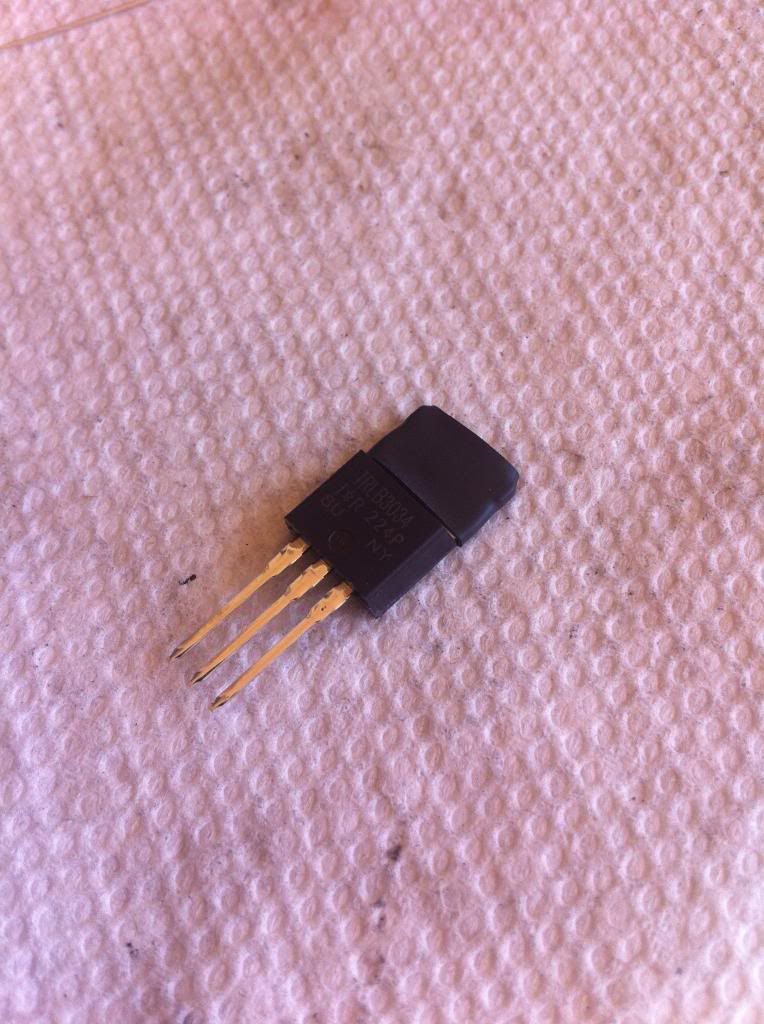
-IRLB3034PBF (IRLB is just a brand. PBF indicates Lead Free) There are others you can use, but these are arguably the best for most set ups.
-22k ohm resistor (1)
-100 ohm resistor (1)
-various sizes of heat shrink
-soldering iron and solder
-heat gun
-12-16awg wire
-22-24awg wire
-always handy to have a 3rd hand tool
 Please note
: you can ruin the MOSFET by heating it up too much, so take your time and let the solder and MOSFET cool down.
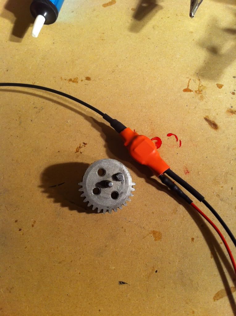
MOSFET & resistors
So lets begin.
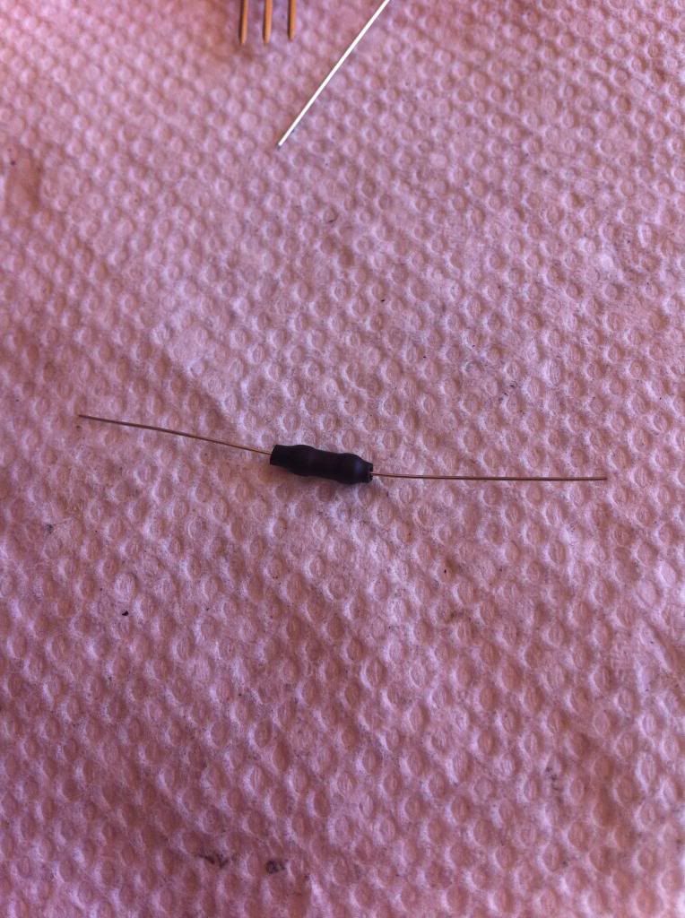
I like to start out by insulating the resistors and mosfet with heat shrink like so:
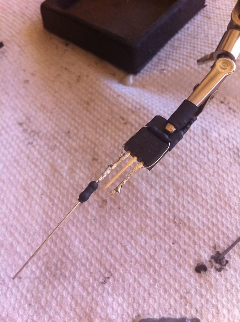
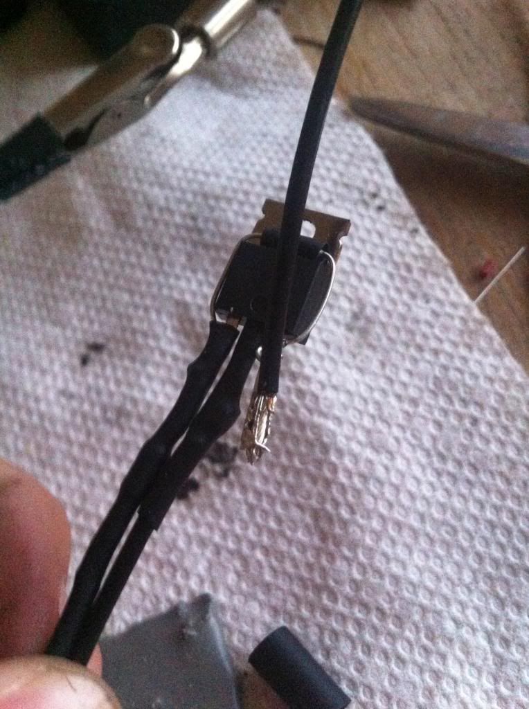
Next, take your 22k resistor and place it as pictured below (the one on top) and wrap the legs around the MOSFET, down to the Gate and Source leads (outside prongs). Solder them to the prongs. Then take your 100 ohm resistor and solder it to your Gate lead (left prong). It should look similair to this:
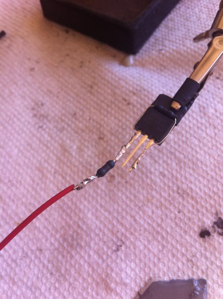
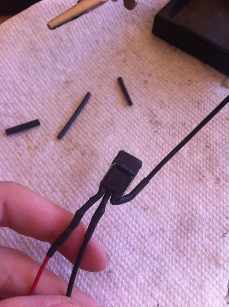
If this is your first time, take ~15 inches of your 22awg wire. You are better off having too much than too little. Solder the 22awg wire to the resitor like so (note that you will need to cut the extra) :
Insulate your work with heat shrink. Use your heat gun. Get some water, take a drink, and wait for it all to cool down.
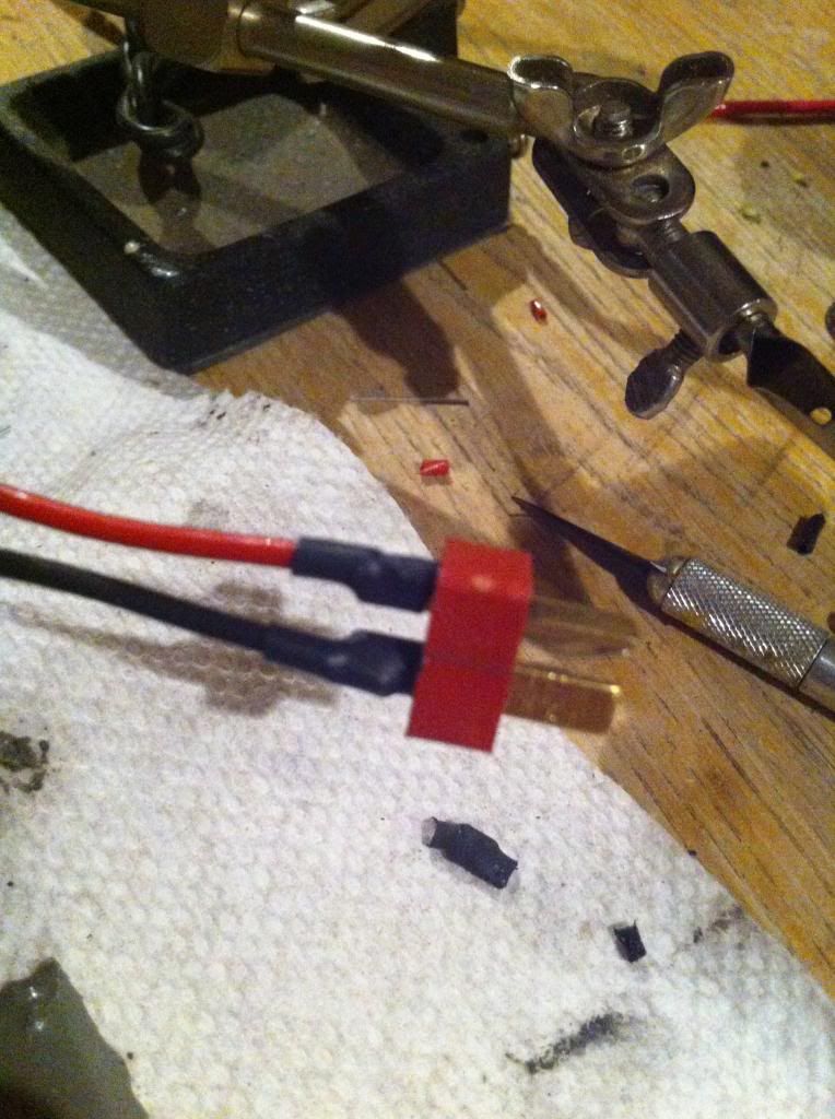
Moving on. Take your negative 16awg wire and solder onto the Source (right prong). I usually solder this wire coming from the top, not the bottom as pictured. It will make sense later. This wire will go to your deans plug.
Put some heat shrink over it.
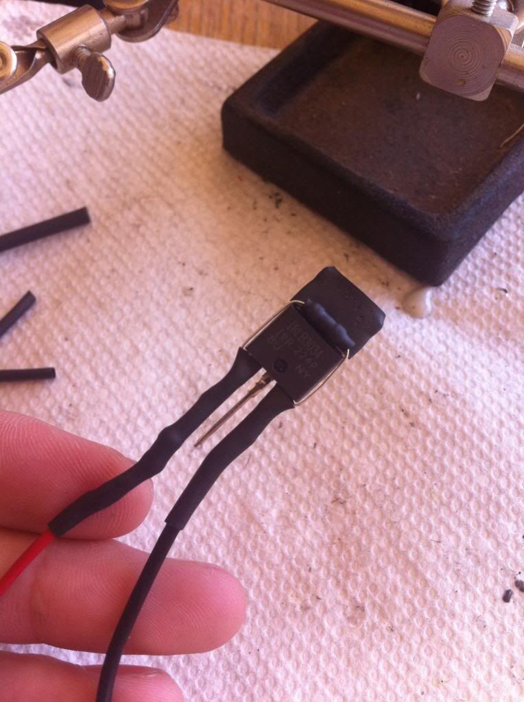
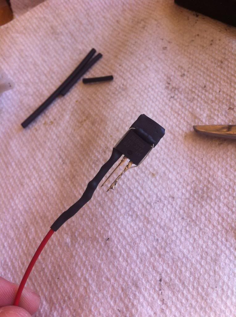
Bend the Source (right prong) upwards. If you soldered the wire from the top, there is no need to bend the Source…
This is what i meant by soldering from over the top. (the Gate is positive wire, it just has long heat shrink..)
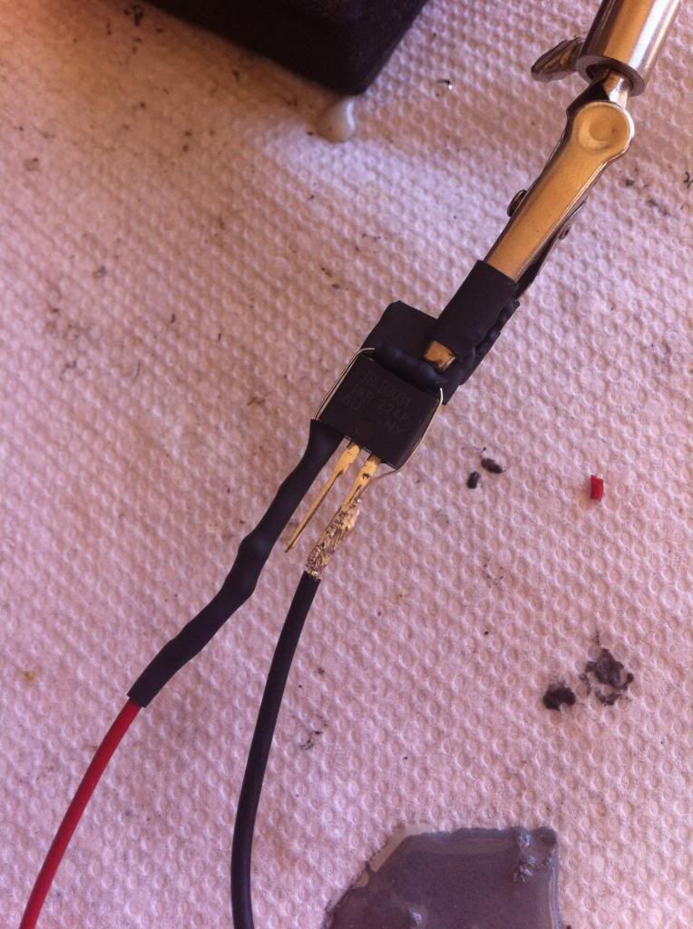
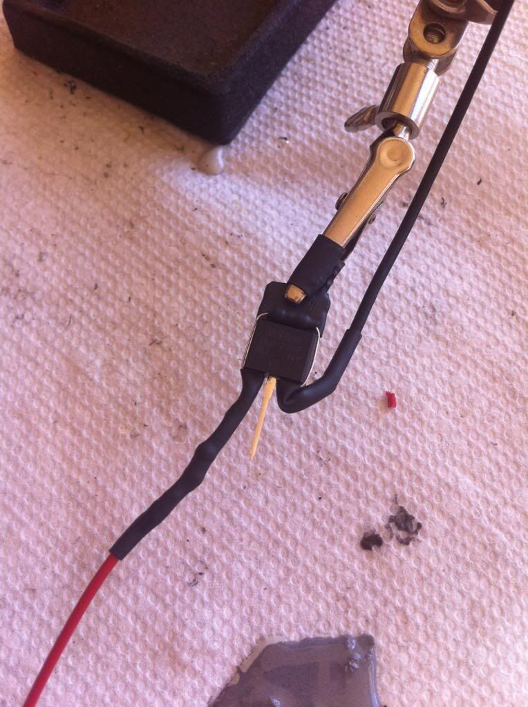
Take more negative 16awg wire. Solder to the Drain (middle prong). Insulate your work. This wire will go to the negative motor tab, so its generally ~16inches depending on the gun.
Finally, take a larger piece of heat shrink and put it over everything. Heat it so its tight, and you're done!
 Part ll. Installing to v2 M4 gearbox
Items needed:
-MOSFET
-solder
-banana connectors*
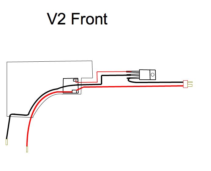
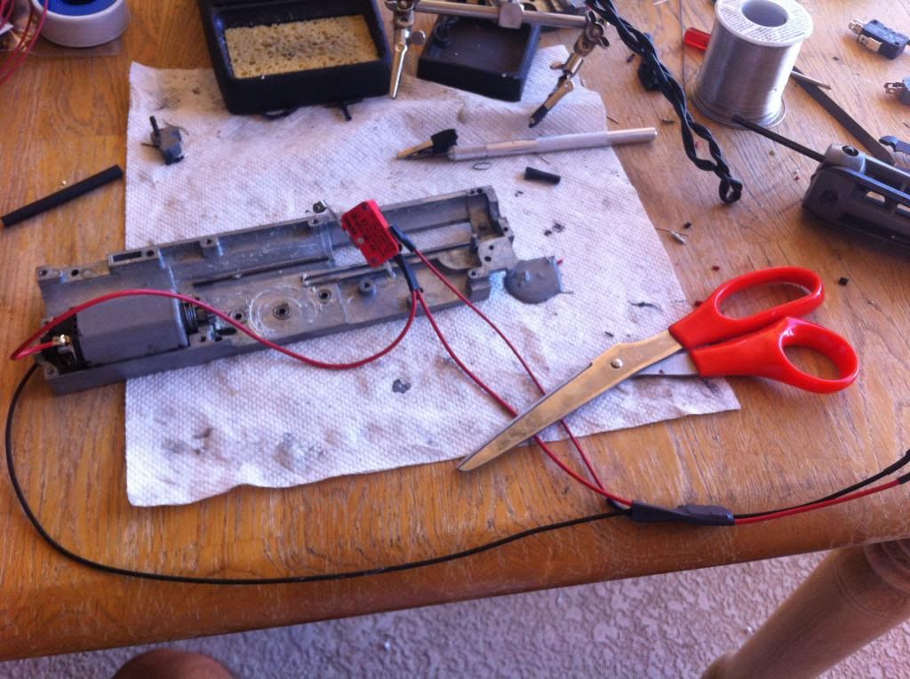
Here is a diagram of a front wired v2 gearbox. Note that the resistors arent shown for simplicities sake..
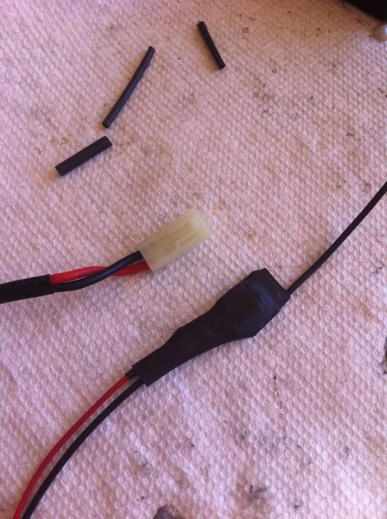
An actual picture. Sometimes soldering the two wires on one tab can be difficult. This isnt a very good example.. But you get the point.
Now installed:
 Please note:
 when wiring a mosfet to the front, it wont fit through the upper receiver. Well how do we fix this?..
With banana style connectors. I typically use the 2mm golden plugs. You can get them at most hobby stores.
Sometimes the plugs like to come undone. If this happens, either put heatshrink over the plugs or electrical tape.
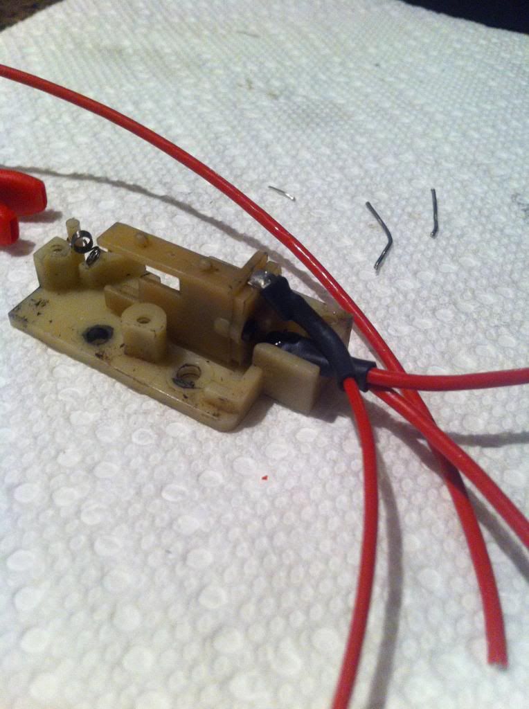
 Part III. Installing to micro switch
Items needed:
-soldering iron & solder
-heatshrink
-completed mosfet
This is for people who want to run a MOSFET to anything with a micro switch. I've searched online for a guide on this but never found one I liked, so here's how its done.
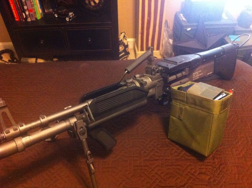
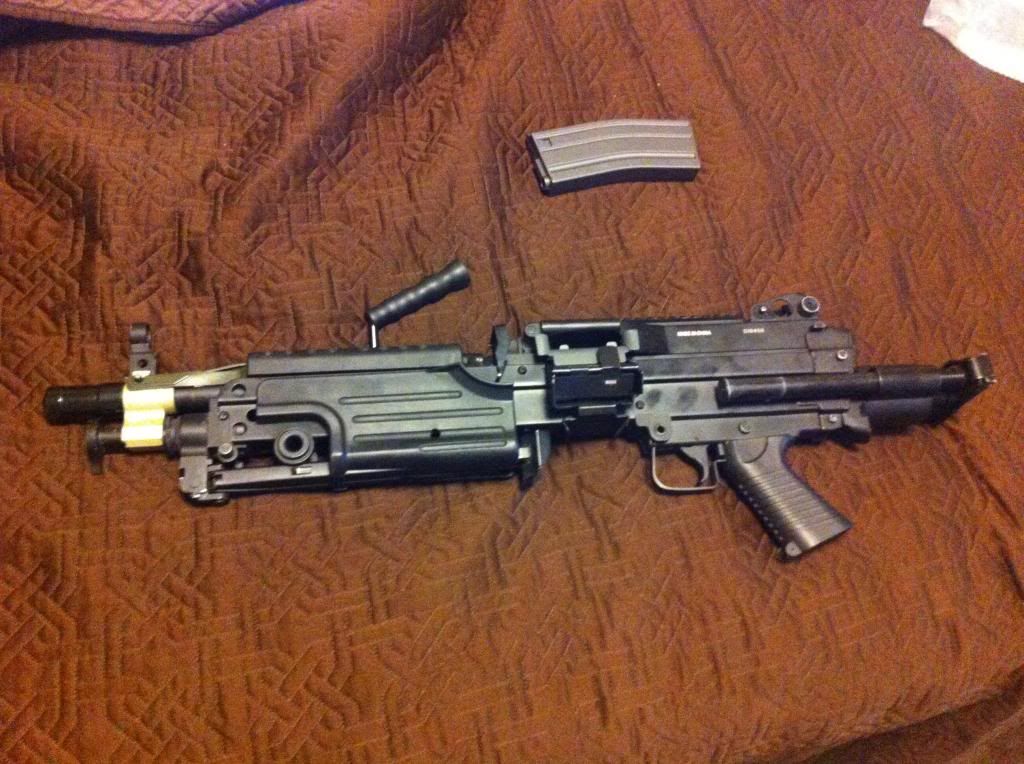
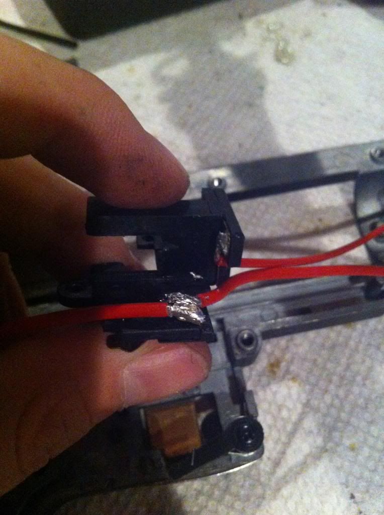
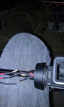
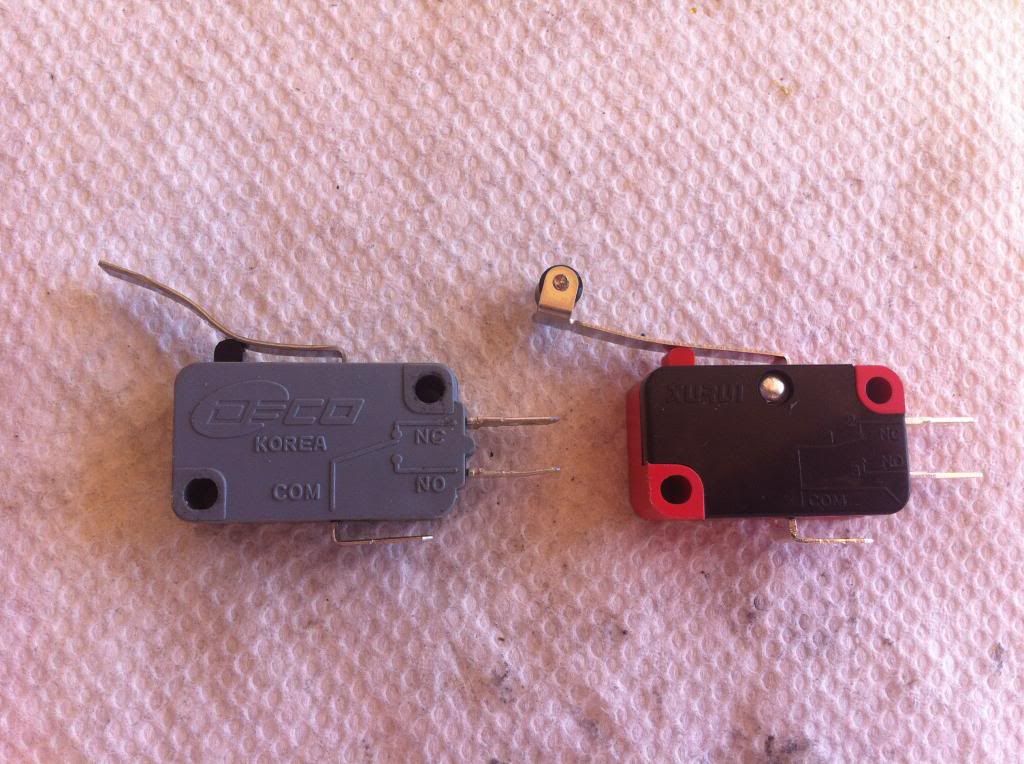
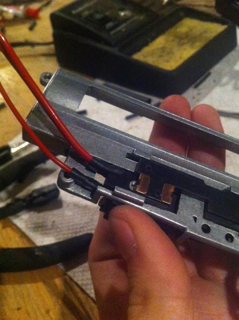
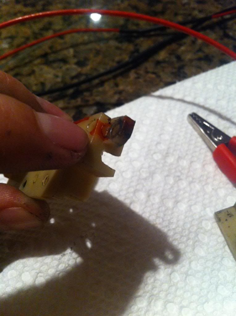
Here are 2 different style switches. You can use either, but the roller type needs to be cut and moved. The switch on the left is a standard 15A from an A&K m249.
First, solder your 22awg wire to the top prong. I find it easiest to put the wire through the hole in the prong, then soldering over. (Dont forget to put heatshrink over the wire)
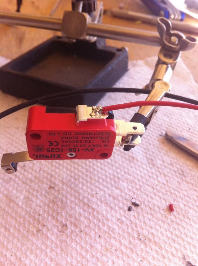
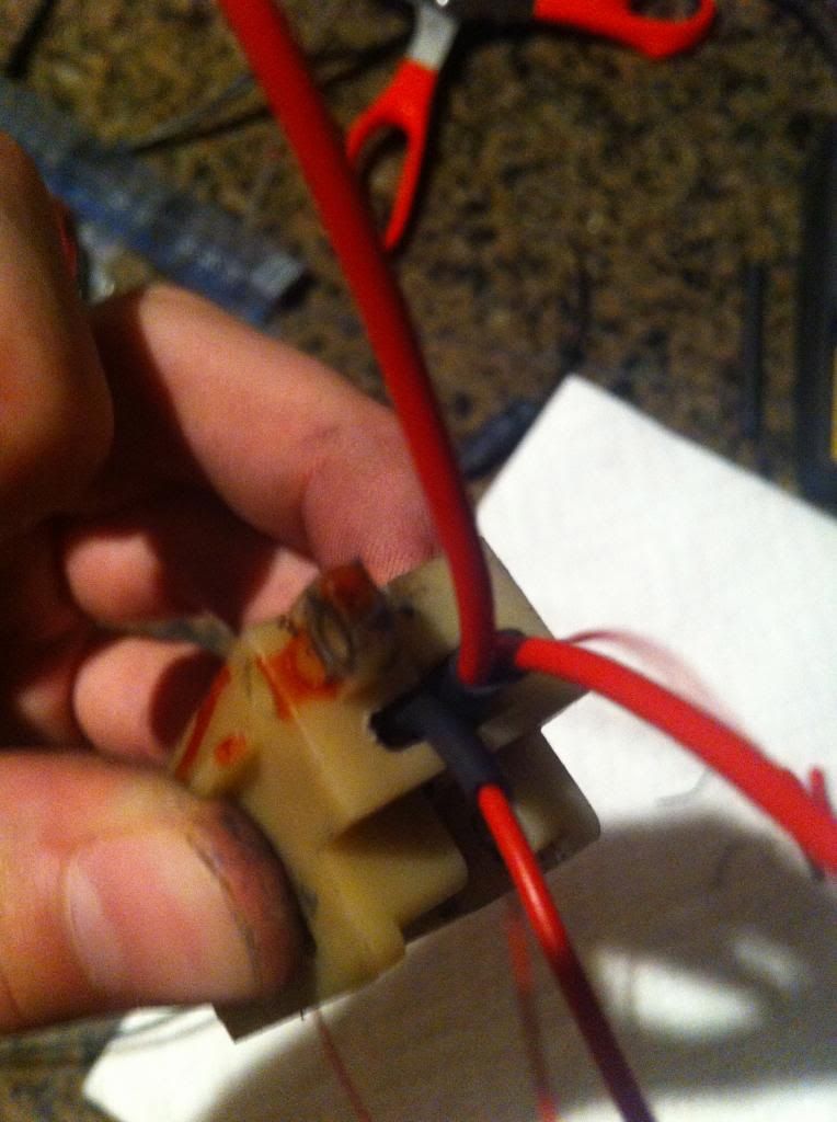
Then, the 2 other positive wires go to the middle prong. Insulate with heatshrink.
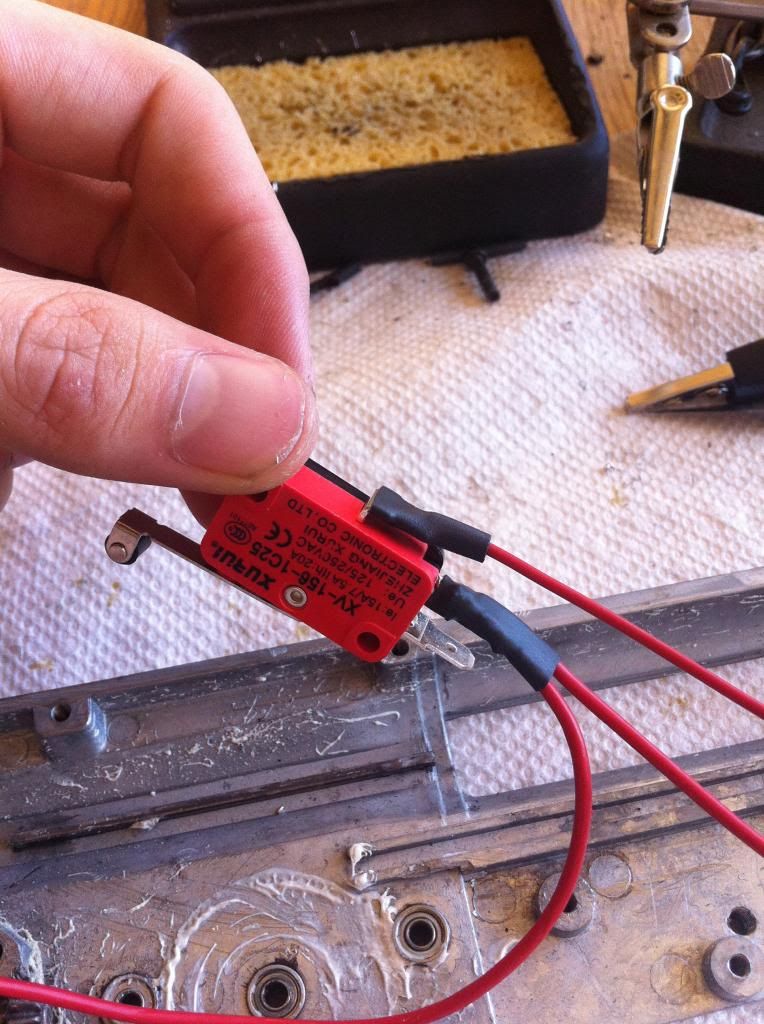
This is how it should look altogether when wiring a MOSFET into a LMG with micro switch
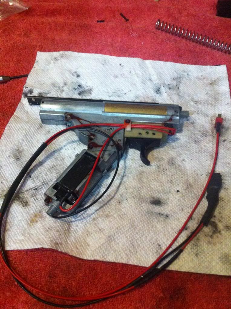
 Part IV. Installing to v3 AK gearbox
 Items needed:
mosfet
soldering iron & solder
heat shrink
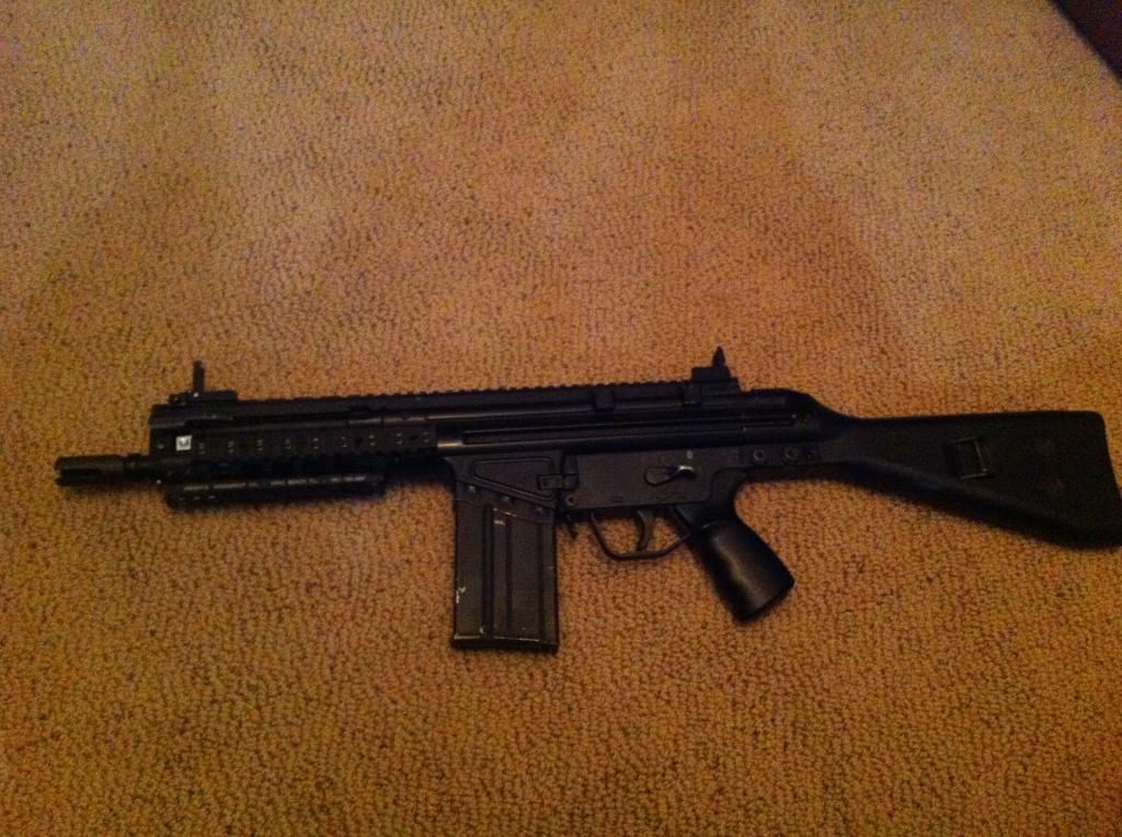
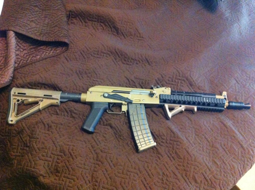
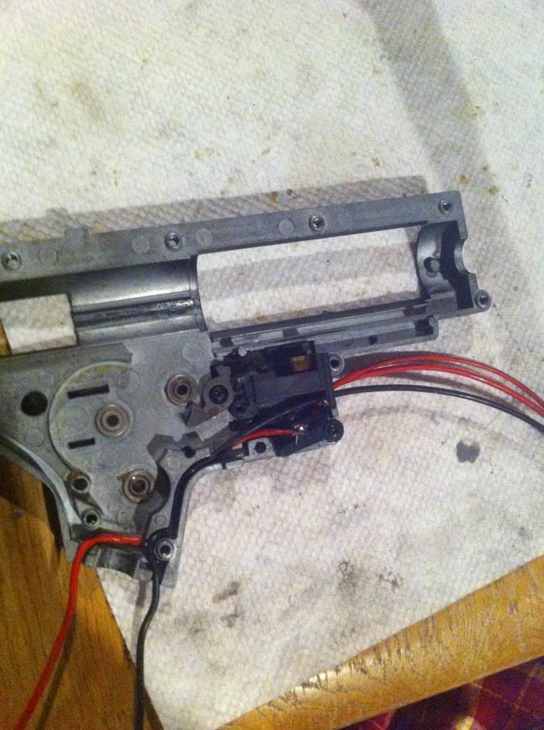
basically, a v3 AK wired to the back looks like so:
Note:
Pretty sure you can swap the placement of the positive wires if its easier.
You dont need to open the gearbox to install a mosfet to an AK
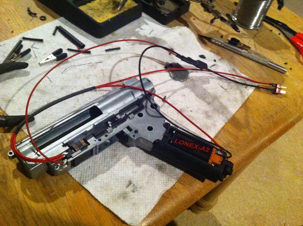
The 2 main (large) positive wire are soldered to the top contact, and the smaller to the bottom. It helps to put heat shrink around them for added strength. (Yes, two wires are on the top, its just hard to see because of my professional picture taking skills…)
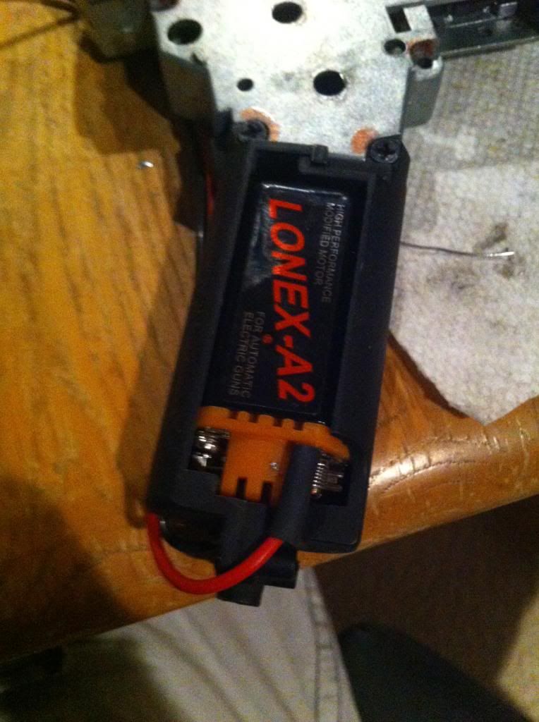
And on the motor tabs also:
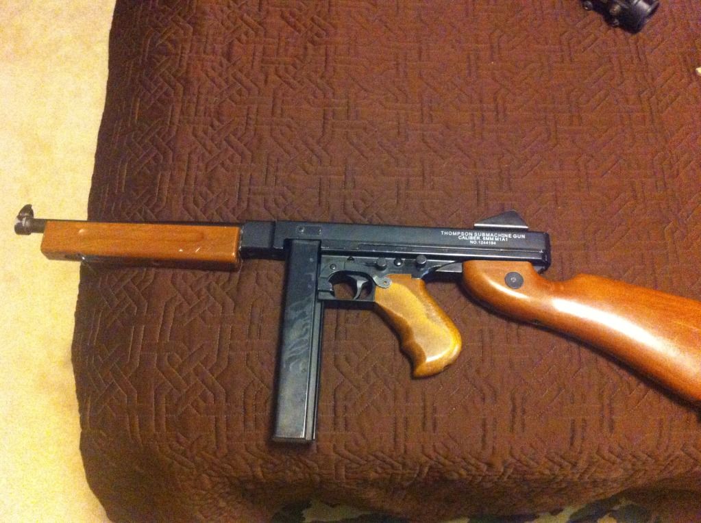
 Part V. Installing to v6 Thompson gearbox
Parts needed:
Soldering iron & solder
heatsrhink
MOSFET
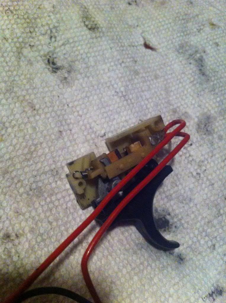
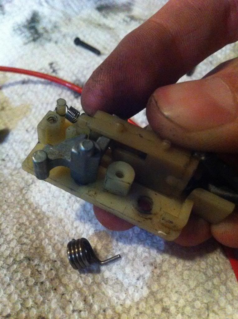
Installing a mosfet to a thompson is quite simple because you dont need to open the gearbox at all.
Here is what your opened trigger assembly will look like.
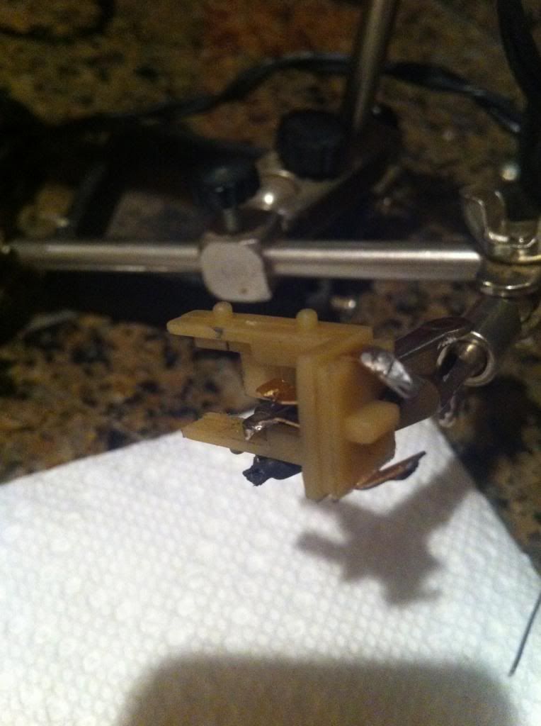
Desolder the wires
Get this part out
The two main 16awg positive wires go here:
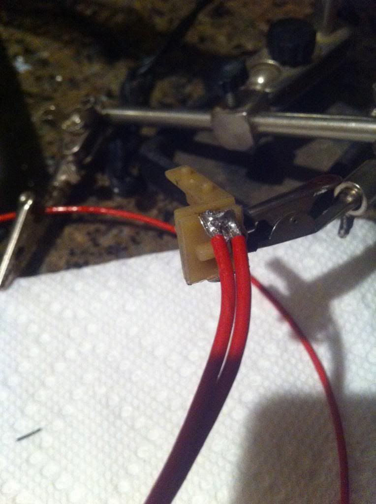
And the small positive on the other. Dont forget heat shrink
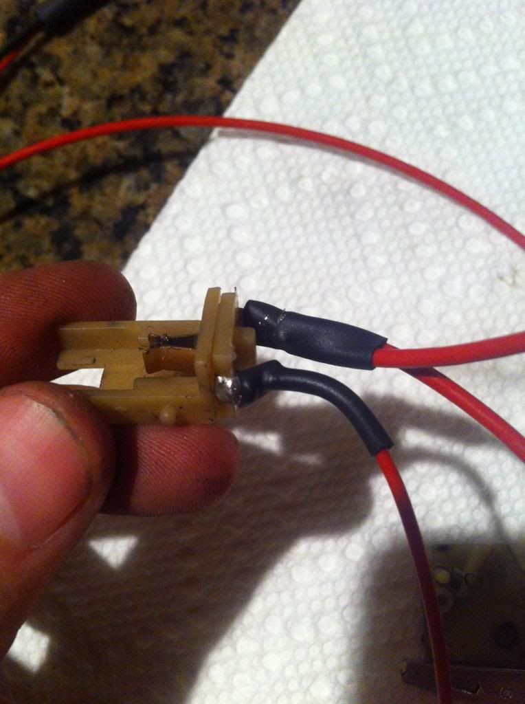
When you put it back into the assembly it'll look like this:
Sometimes it'll be difficult to close the top half back on because of all the wires. I dremel out this part of the upper portion of the assembly:
Now, the wires arent so pinched
And you are done:
For those who have trouble with the reassembly of the trigger, this may be helpful. I put this arm in last. It might take some time.. more difficult than V3's IMO.
 Part VI. Correcting AoE
Items needed:
-sorbo or faucet washers
-cyanoacrylate (super glue)
-dremel
First of all, what is AoE? Angle of Engagement. The AoE between the sector gear and piston teeth actually.
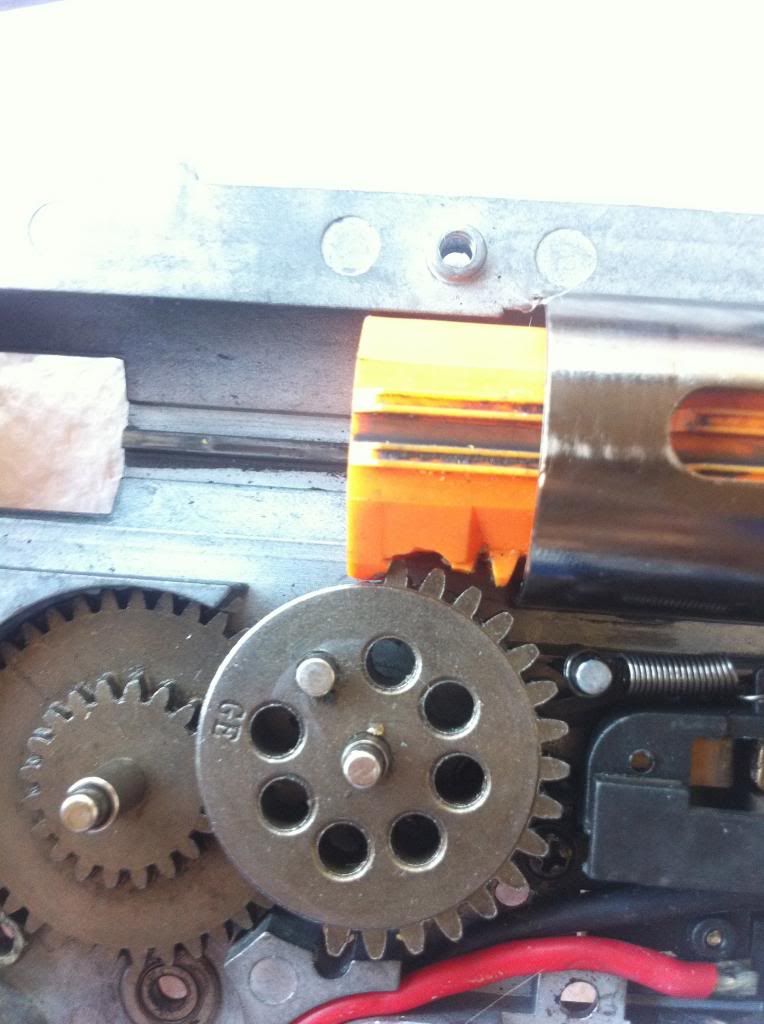
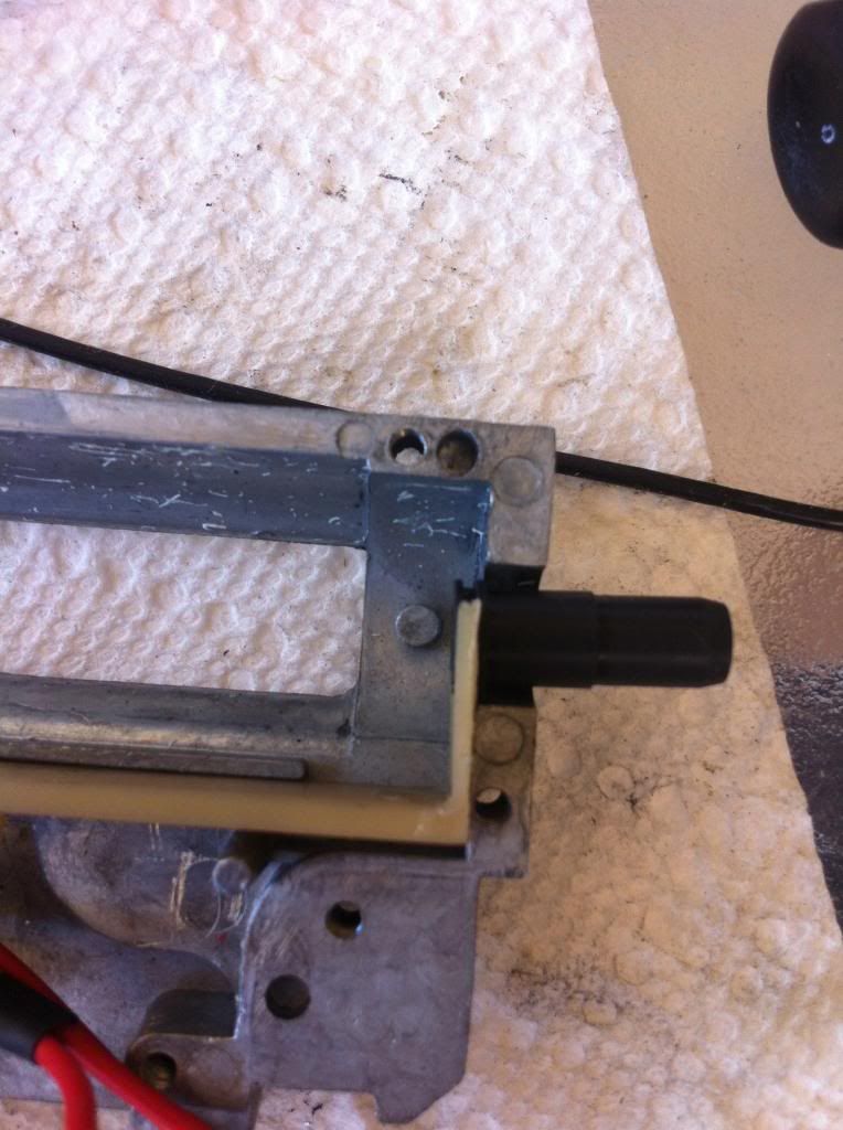
See here, this is what most AEG's come like:
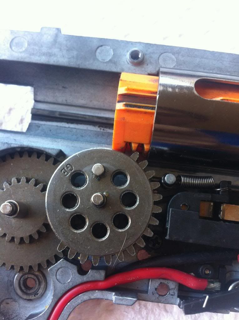
The pickup tooth on the sector gear is actually coming into contact with the 2nd tooth. So, take a dremel and shave the 2nd tooth off. (also notice how far the piston is coming out of the cylinder)
"On plastic pistons soldering iron works well to remove extra teeth especially on pistons with reinforcement along the outside edges of the teeth," ThatGuy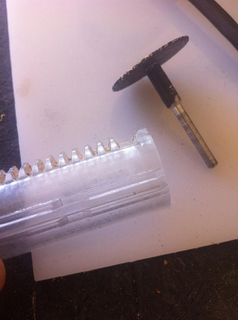
Now, when you put it back together it'll look about like this. This is… better.. but not exactly what we want.
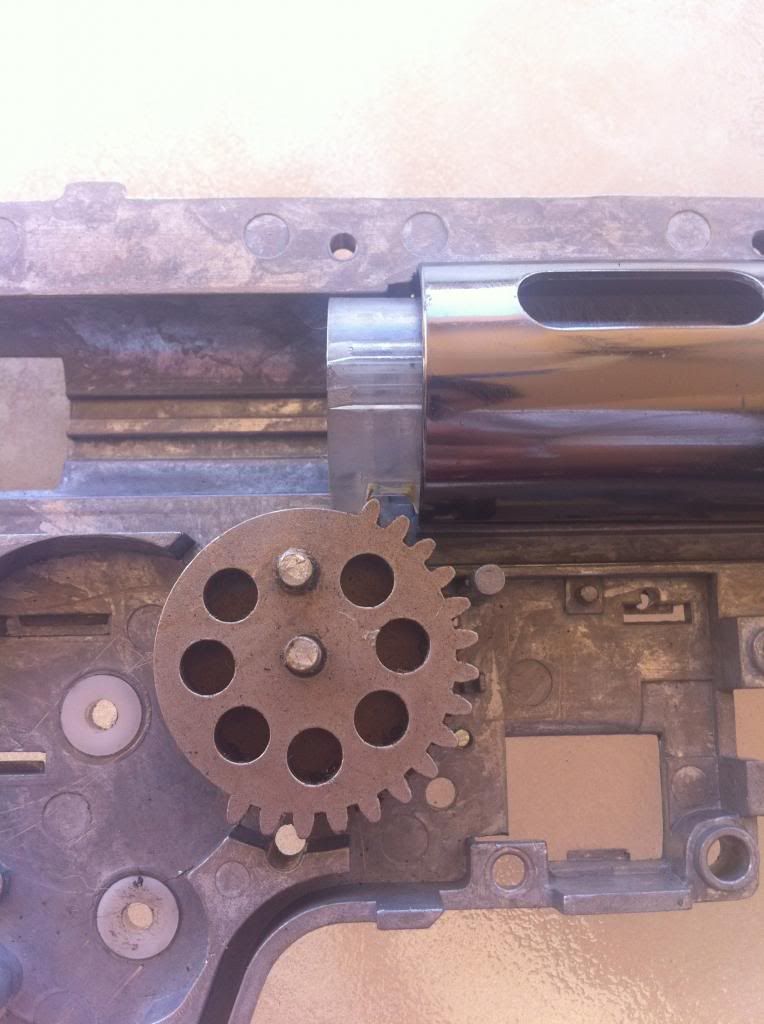
We want the sector gear's pickup tooth to engage at 12:00. We need something to take up a couple mm's, either on the piston head or cylinder head.
My preference is Sorbothane, or sorbo for short. Sorbo is a shock obsorbing material that prolongs your gearbox's lifetime.
You can also use faucet washers in place of sorbo.
First, remove the original padding and clean any residue. (not my picture)
Next, glue the sorbo pad on. Then, glue the original pad over the top. (this can be done with just glueing the sorbo over the original pad. However, this method will cause the sorbo to wear faster)
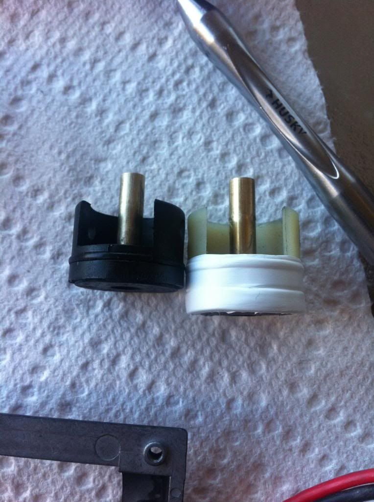
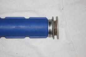
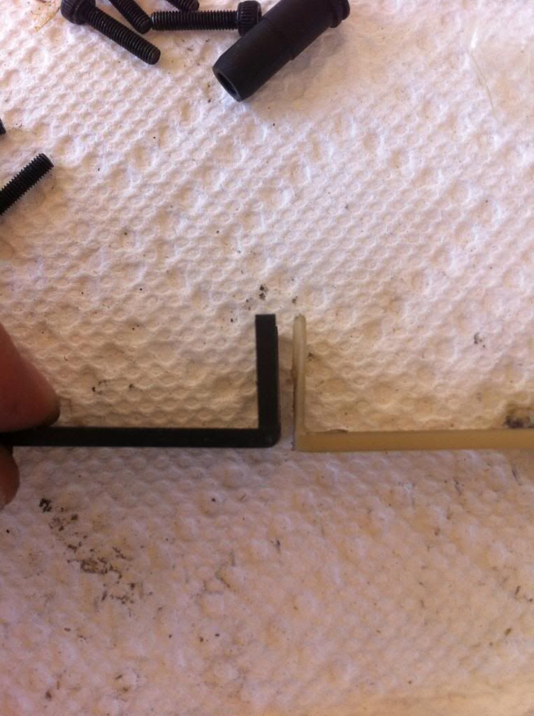
On the left is a stock cylinder head. On the right is one with sorbo.
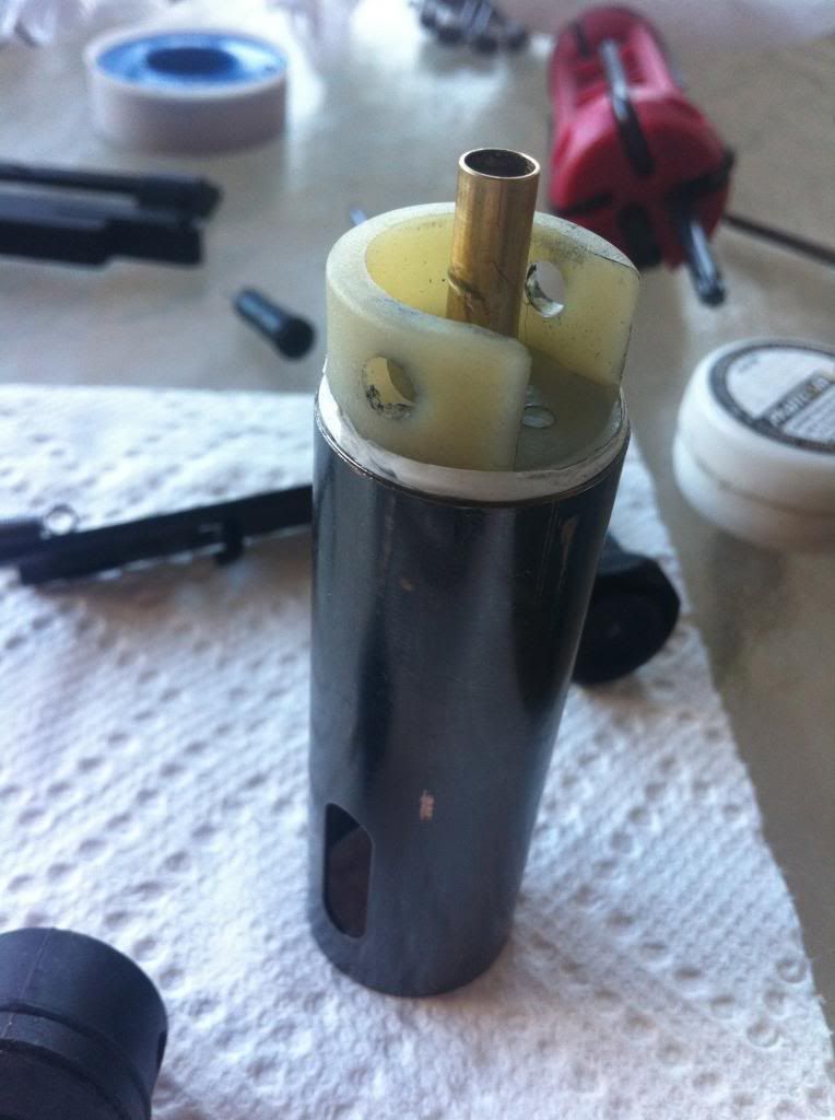
Squeeze your cylinder head into your cylinder.
Put it all back into the gearbox and check the AoE. Hopefully, it will be around 12:00 so we can have the best surface contact between the correct teeth.
This isnt the prettiest example out there. Most of the time, you will also need to trim the 3rd tooth, and maybe more.
Here is an example with spacers on the piston head:
 Part VII. Radiusing shell window
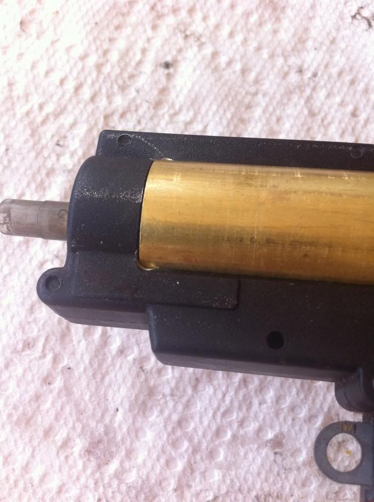
This is a little trick that prevents the front end of your gearbox from cracking. Here is a normal gearbox. Some come already radiused
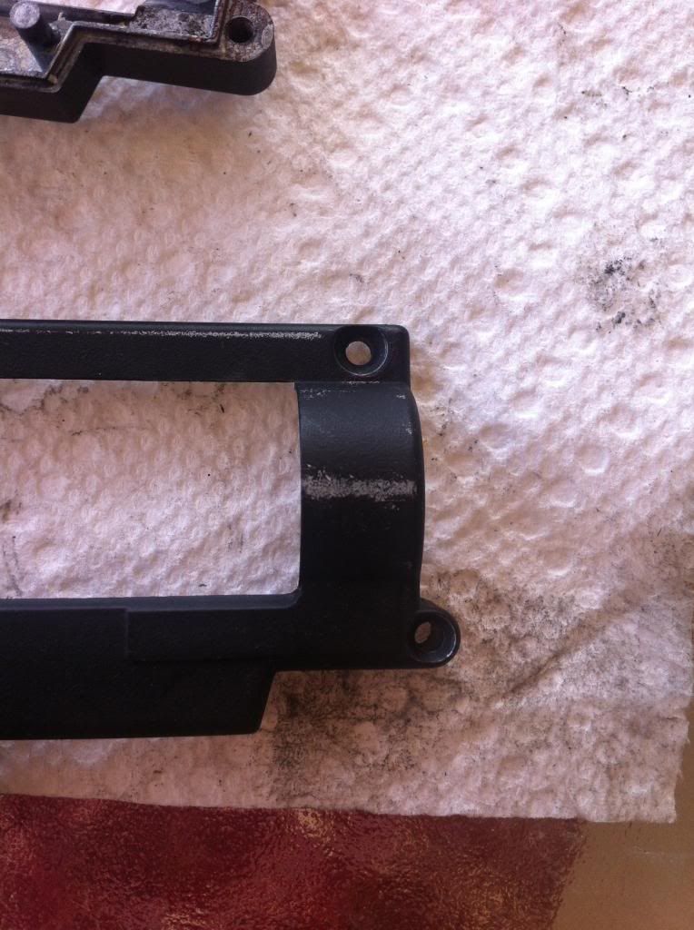
All you do is take a small bit dremel or rat tail file and round off the inside corners of the gearbox windows. And that's it
 Part VIII. Shimming
 So what is shimming? Basically, its applying little "shims" on the gear axles to allow the gears to mesh properly. Bad shimming can cause a hot motor, premature wear, screeching noises, and sometimes gearbox lockups
When you will need to reshim:
-new gears
-new motor
-new bushings/bearings
-new gearbox shell
-after 50k rounds its a good idea
-and most importantly: as soon as you buy a new gun. No gun comes shimmed perfectly out of the box. No, not even VFC's self-shimming gears.
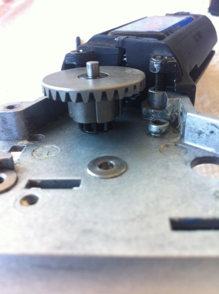
You start by shimming the bevel gear to the pinion gear
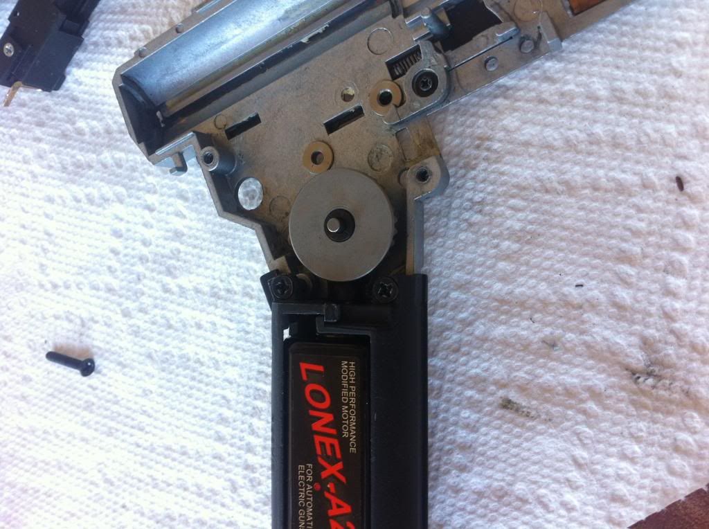
I couldnt manage to get a picture of how the teeth are meshing here (you try to squeeze a fat iphone there…) but this is where you want to adjust your motor height. It's easy to see when you're actually doing it. This is where having a gun with a motor cage is great, unlike a v2.
Once you've adjusted the motor height, start placing shims one at a time underneath or above the bevel gear until it is meshing perfectly with the pinion. Close the gearbox and check how it looks and feels each time you add or remove a shim. Take your time, this is the most important step.
Once you shimmed the bevel-pinion, you can remove the motor cage.
Now you go to the bevel-spur. Pretty much the same process here. You usually want to keep the spur pretty low, but so that it still has clearance from the shell, yet it meshes with the bottom teeth from the bevel. This picture is not a good example but you get the point.
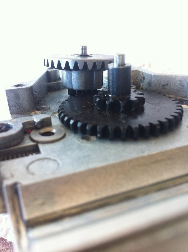
Keep placing shims, closing the gearbox, and spinning the gears to feel if they run smooth and silently. I feel like this is all that is necessary so I wont be finishing up with the spur-sector. When all is said and done, you should be able to spin the gears around 5-9 times. It should feel smooth, and sound pretty quiet.
Its always a good idea to assemble the gearbox with just the gears, then put the motor cage on, plug a battery in, and cycle the gears. If it sounds bad, it is bad. Its your guns way of saying, "Green, you suck at shimming." Or something along those lines..
Dont rush this. Too tight and it'll cause problems. Too loose and it'll cause problems. So do it right the first time.
Part IX. Airseal modsItems needed:
teflon tape
o-rings
greases/lubes
some source of heat (heat gun, lighter, etc)
glue
1. Cylinder head
2. Piston head
3. Air nozzle
Airsoft AEG's shoot a fixed volume of air. So… let make sure we get all of our air.
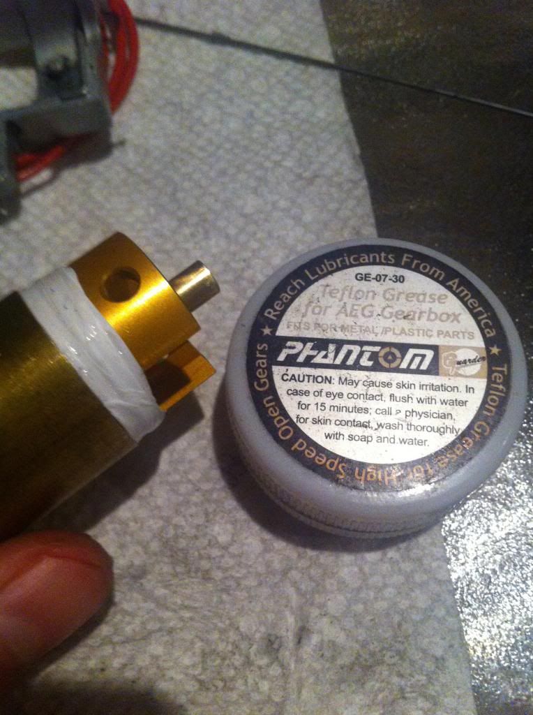
1. Lets start with the cylinder head. Most come stock with 1 weak o-ring. Some with two, which is what i will be using here. Cool.
Take that handy teflon tape and wrap it around about 3-5 times.
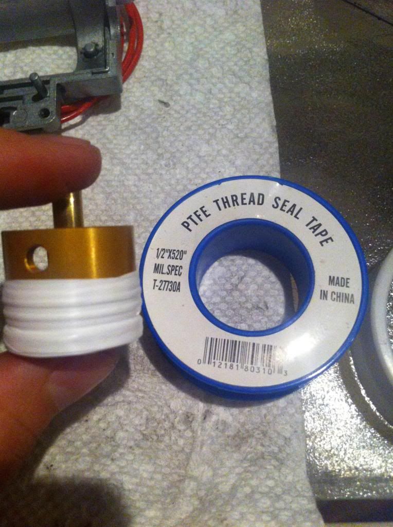
Now all i had available is this teflon grease… so put some teflon grease around the tape and shove it into your cylinder. You can use other sealant's for better results
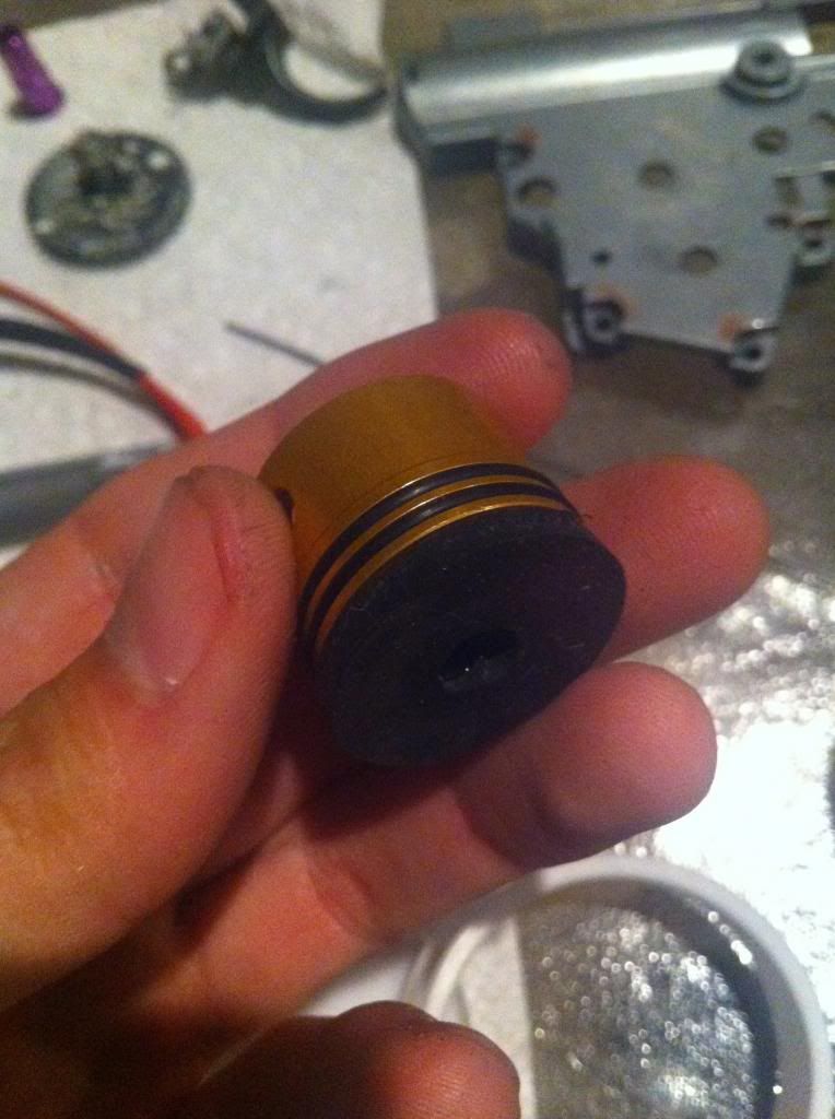
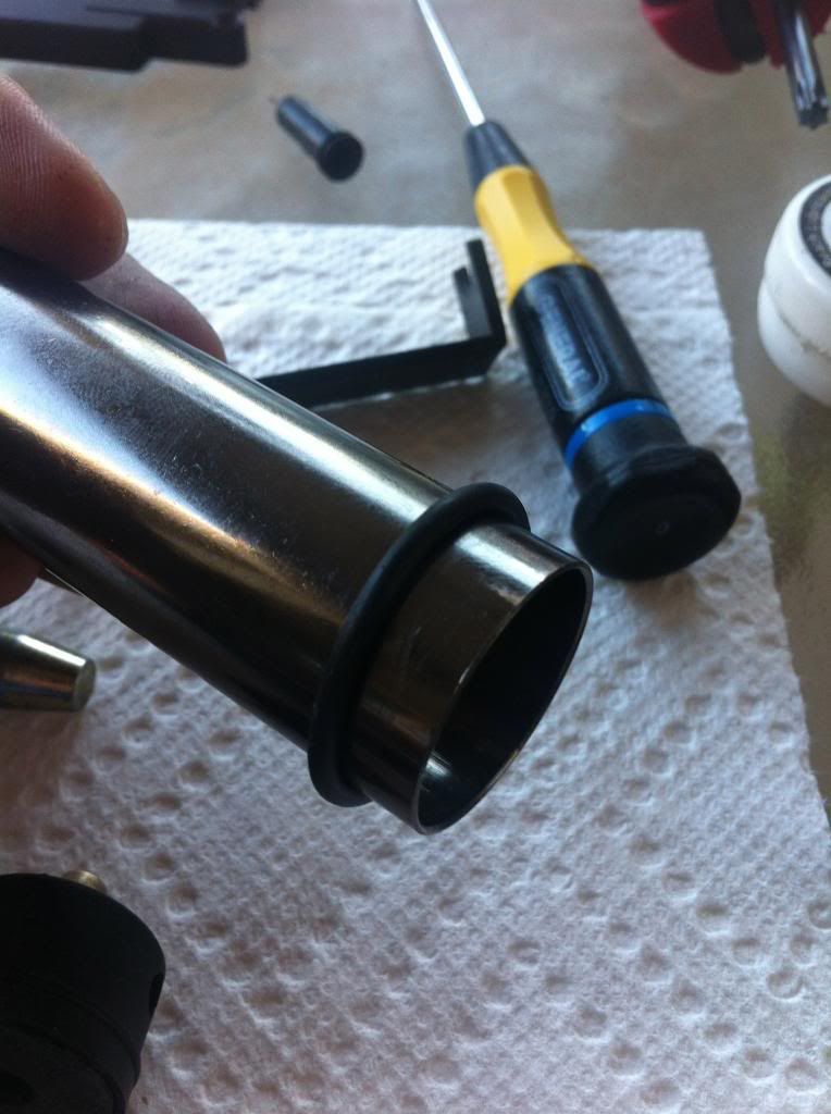
2. Piston head.
If all you have are stock o-rings, here is a decent way to improve air seal.
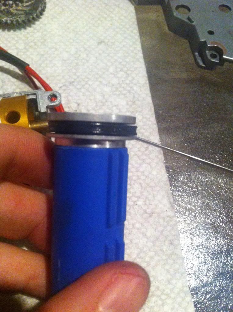
Remove your piston head and place it around your cylinder. Apply (lightly) whatever lubricant you're planning on using around the o-ring, and heat it with a heat gun or lighter.
Do not overheat. Move it around and let it cool.
Another thing you can do is simply buy better o-rings. I personally prefer viton O-rings, as they have 2 "lips" for better seal. Or you can buy your traditional #14 o-rings.
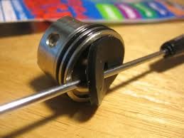
3. Air nozzle
Most air nozzles come without an internal o-ring shown below:
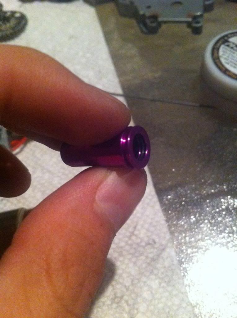
You can place a small o-ring at the bottom of the air nozzle in its place however. After you glue it on so it doesnt come off, be sure that the nozzle can still slide on the cylinder head tube without getting caught or having excessive drag.
Part X. Tappet trimmingItems needed:
Tappet plate
dremel or file
This could be in the airseal section but whatever. Why would you do this? Its easier to explain with pictures, so keep reading.
Normal tappet plate on left, trimmed on the right.
All you do is take a dremel or file and start taking material off the face of the tappet plate.
See now that the tappet plate face is trimmed, it allows the air nozzle to petrude further. This makes the nozzle go "deeper" into the hop up chamber, improving the air seal.
 Part XI. Barrel stabalization
 Coming soon
Part XII. Soldering deansItems needed:
Soldering iron & solder
deans
wire strippers
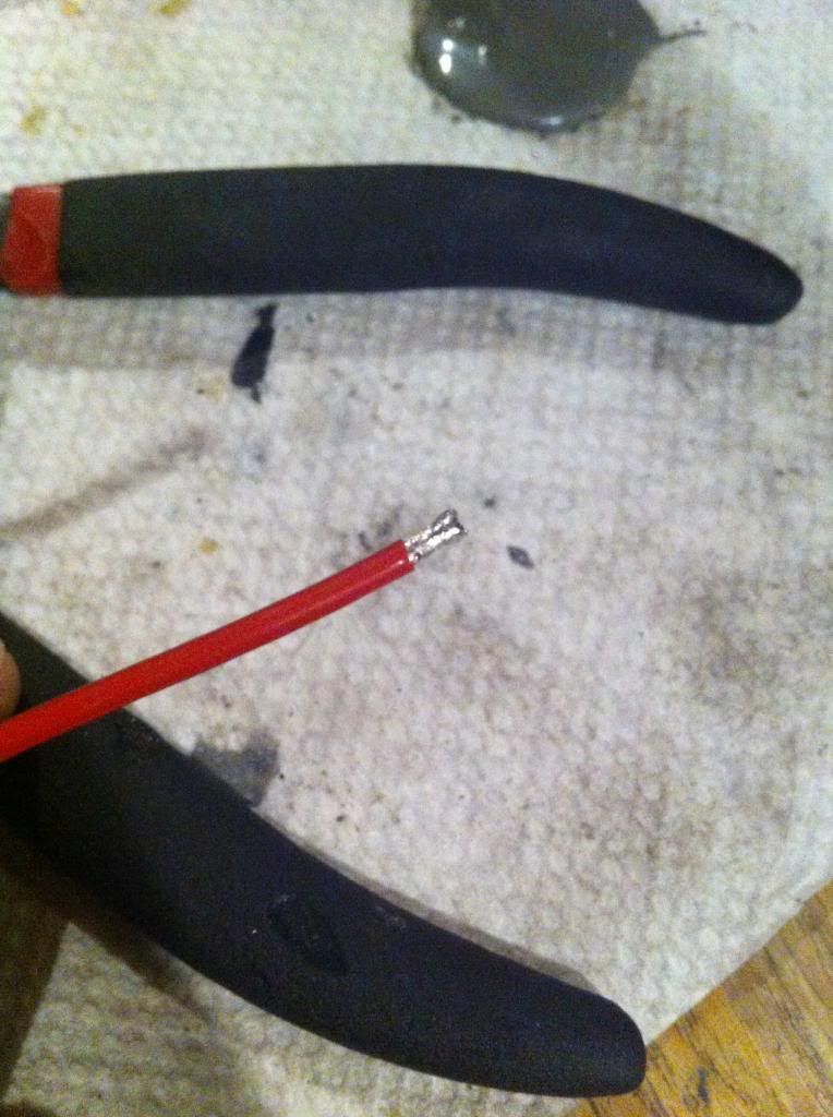
Never cut both wires at the same time.Cut your wire and apply some solder onto the wire.
Also to the deans.
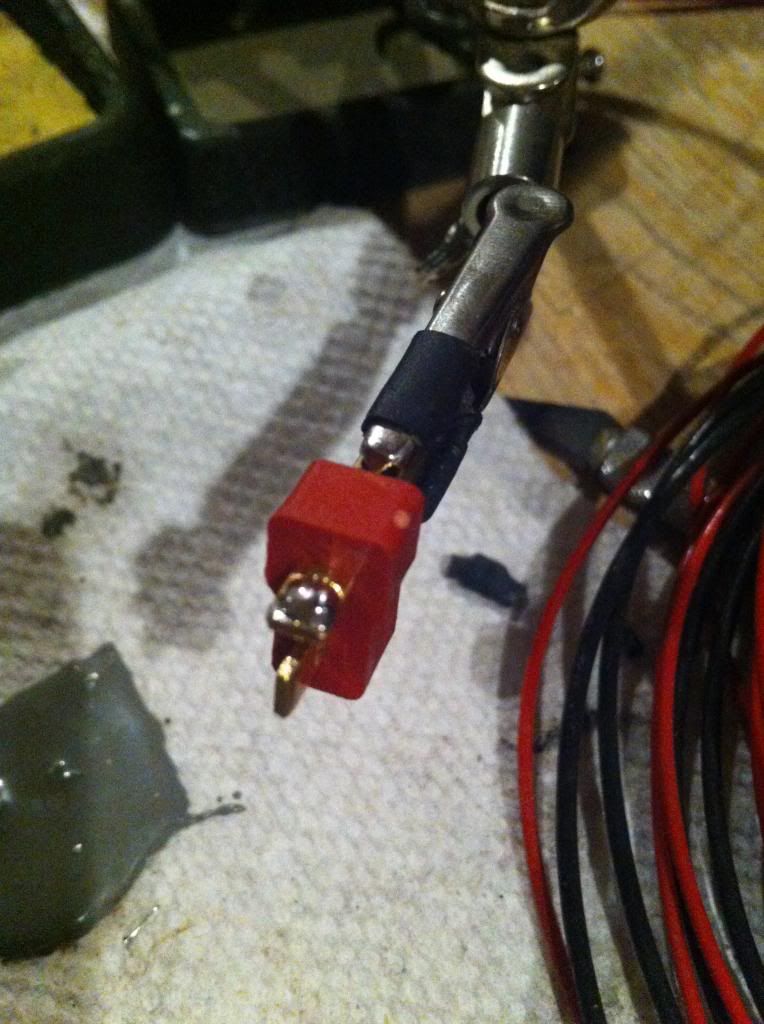
Dont forget heat shrink. Solder the wire to the plug, and insulate with heat shrink.
…And repeat with the other wire
 XIII. Preventing Premature Engagement
1. Short stroking
2. Heavier spring
3. Piston lightening & swiss cheesing
Oh noes, PE is here! PE is the result of the sector gear engaging the piston before the piston has completely cycled. This happens typically when you have a weak spring, speed gears & strong motor, and a heavy piston assembly.
1. Short stroking
Items needed:
sector gear
dremel
This is how to short stroke the gears.
Simply take your sector gear and dremel:
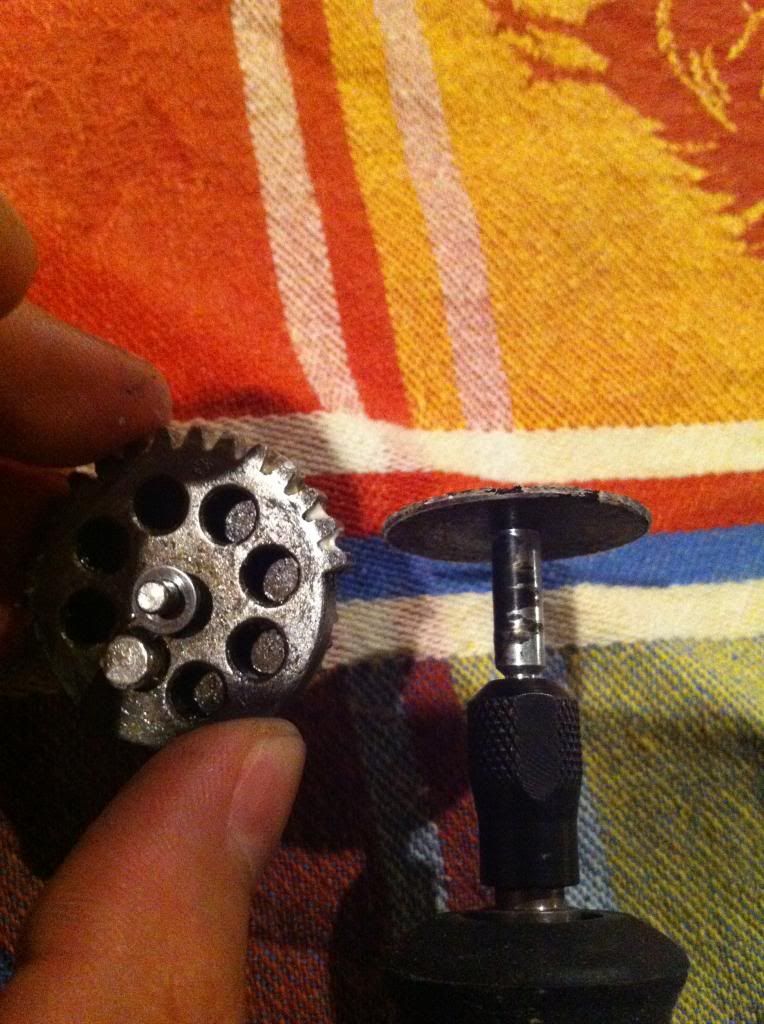
and cut off however many release teeth as you want. This example is SS-1, meaning short stroked 1 tooth.
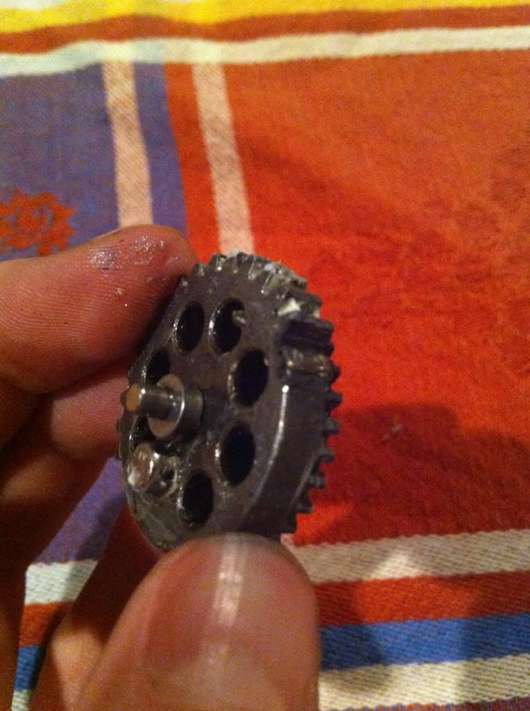
But what does this even do? A) it lowers the fps by about 12-15 per tooth. and B) allows the piston more time to cycle by releasing it sooner.
This is almost always done with this:
2. Heavier spring
Say you have 13:1 gears, neo motor, heavy piston, m90 spring. You're asking for trouble with that spring, but you really want that 300 fps so you can play at vanguard.
So add a m110 spring or so, and SS as many teeth until your desired fps. Simple.
3. Swiss cheesing